Hi Stefan,
Thank you – now OEM works!
Reading sensible numbers for both – current and temperature!
Will move forward…
Thank you!
Yuri
Hi Stefan,
Thank you – now OEM works!
Reading sensible numbers for both – current and temperature!
Will move forward…
Thank you!
Yuri
Hello Yuri,
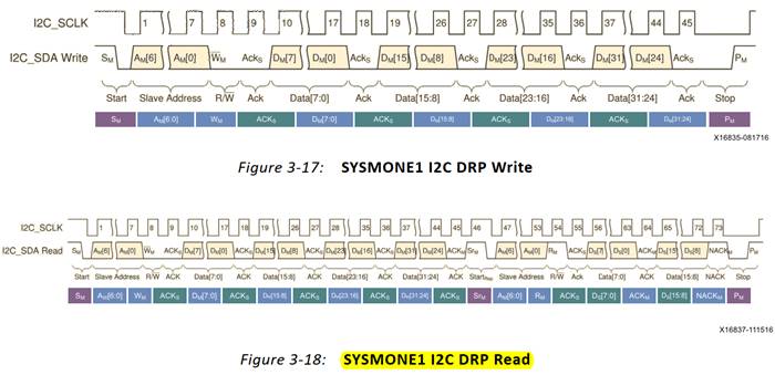
I’m glad to hear that it finally works! The issue was that the data sheet of the IQ60533 is misleading: apparently reading one of the sensor registers requires a single transfer with a repeated start, and not independent write and read transfers as the data sheet suggests.
Given that the IQ60533 uses exactly the same register model as the PIM400KZ, I attach the XML snippet for the relevant sensors from the MUCTPI, this may be useful.
Let me know if you hit any other problems.
cheers,
Stefan
(Attachment pim400kz-sensors.xml is missing)
Hi Stefan,
Yes, that was the problem and thank you for the xml file.
Now will come back to the System Monitor of the FPGA.
Thank you!
Yuri
Hello Yuri,
concerning the FPGA SYSMON, I hope this will just require of correcting the I2C address (7-bit to 8-bit). Let me know if it works with that modification.
cheers,
Stefan
Hello Yuri,
thanks, that’s good news. Let us know if you hit any other problems.
BTW, would you agree to share the code of the sensor driver for the FPGA SYSMON? If this is ok with you, then we could then simply add it to the ipmc-sensors subdirectory in the ipmc-project repository as an example for other potential users.
cheers,
Stefan
Hi Stefan,
Yes, sure, it’s on the git:
https://gitlab.cern.ch/atlas-l1calo/firmware/hubrod-ipmc/-/tree/master/ipmc-sensors
https://gitlab.cern.ch/atlas-l1calo/firmware/hubrod-ipmc/-/tree/master/xml-common
https://gitlab.cern.ch/atlas-l1calo/firmware/hubrod-ipmc/-/blob/master/ipmc-user/user_oem_examples.c
But it is very simple and read only one temperature register
Cheers,
Yuri
Hi Stefan,
I’m observing some strange behaviour, not sure is this a problem or a feature.
To remind – I (we ![]() ) finally made Power Entry sensors (on MGT_I2C) and Sysmon sensor (on Sensor_I2C) working.
) finally made Power Entry sensors (on MGT_I2C) and Sysmon sensor (on Sensor_I2C) working.
There are also several DCDC convertors on Sensor_I2C, so I made an OEM command for one of these DCDC sensors.
That works and provides the correct value, so I made driver and add this sensor to the list – and what I observed:
So, I removed Power Entry and Sysmon sensors, only DCDC left:
So, I removed the DCDC sensor from the list and put back to the list Power Entry and Sysmon:
Any ideas how to proceed and which tests to make to understand the issue? Is this the IPMC or the Shelf Manager?
Thank you,
Yuri
Hello Yuri,
What do you mean by wrong value? Maybe the scaling factor in the XML is wrong?
BTW, what part number are the DC/DC converter(s)? If the code on gitlab is up-to-date, I could have a look.
I don’t understand your last point, if you deactivate the module you can’t see the SYSMON sensor, since the FPGa is not powered?
Hi Stefan,
What do you mean by wrong value? Maybe the scaling factor in the XML is wrong?
XML is correct, when I used the DCDC only I saw initially the correct value – 12V.
BTW, what part number are the DC/DC converter(s)? If the code on gitlab is up-to-date, I could have a look.
Attached are the DCDC MDT040 data sheet and the TPS40400 I2C interface chip.
I updated the code on the git.
I don’t understand your last point, if you deactivate the module you can’t see the SYSMON sensor, since the FPGa is not powered?
The Sysmon gives the wrong value as the FPGA is not powered, but IPMC still can read (the Power Entry sensors are correct as they are powered):
Pigeon Point Shelf Manager Command Line Interpreter
Command issued via IPMB, status = 0 (0x0)
Command executed successfully
…
82: LUN: 0, Sensor # 5 (“HUB_IQ65033_CURR”)
Type: Threshold (0x01), “Current” (0x03)
Belongs to entity (0xa0, 0x60): FRU # 0
Status: 0xc0
All event messages enabled from this sensor
Sensor scanning enabled
Initial update completed
Raw data: 0 (0x00)
Processed data: 0.000000 Amps
Current State Mask: 0xc0
82: LUN: 0, Sensor # 6 (“HUB_IQ65033_TEMP”)
Type: Threshold (0x01), “Temperature” (0x01)
Belongs to entity (0xa0, 0x60): FRU # 0
Status: 0xc0
All event messages enabled from this sensor
Sensor scanning enabled
Initial update completed
Raw data: 38 (0x26)
Processed data: 24.480000 degrees C
Current State Mask: 0xc0
82: LUN: 0, Sensor # 4 (“HUB_SYSMON_TEMP”)
Type: Threshold (0x01), “Temperature” (0x01)
Belongs to entity (0xa0, 0x60): FRU # 0
Status: 0xc0
All event messages enabled from this sensor
Sensor scanning enabled
Initial update completed
Raw data: 2 (0x02)
Processed data: -269.080000 degrees C
Current State Mask: 0xc0
Thank you,
Yuri
(Attachment ge_mega__d_lynx_40_amp_pmbus_MDT040A0X.pdf is missing)
(Attachment tps40400.pdf is missing)
Hello Yuri,
I had a look at your code and the sensor driver is too simple I’m afraid. Before accessing the bus, you need to check if it is available. You also need to check and handle the return status of the I2C access functions. Check for example the sensor driver code of the temperature sensor on the IPMC here:
https://gitlab.cern.ch/ep-ese-be-xtca/ipmc-project/-/blob/master/ipmc-sensors/sensor_mcp9801.c#L112
Finally, as I already told you before, you need to add debug outputs to your sensor driver to understand what is going on.
cheers,
Stefan
Hello again,
concerning the FPGA SYSMON sensor (and any other sensors that are on payload power), the sensor driver should be able to handle the fact the the payload power is off. The DS75 sensor driver from PigeonPoint is an example of how to handle sensors that can be unavailable, see here:
https://gitlab.cern.ch/ep-ese-be-xtca/ipmc-project/-/blob/master/ipmc-sensors/sensor_ds75.c#L216
cheers,
Stefan
Hi Stefan,
OK, as you said, the sensor driver is too simple and before accessing the bus, one need to check if it is available – I agree with that. Just to remind – I use the generated driver template from you:
https://cern-ipmc.web.cern.ch/sensors
In this template there are two functions:
unsigned char read_sensor_dcdc(unsigned char *value, unsigned short i2c_addr, unsigned short reg)
In this function I describe how to read sensor
The second function:
static char sensor_dcdc_fill_rd(sensor_t *sensor, unsigned char *msg)
calls the previous one.
I looked into your suggested file “sensor_mcp9801.c”.
In this file, the check is performed in the function:
static void sensor_mcp9801_update_reading(unsigned char num, unsigned char flags)
The i2c bus availability is done in this function.
I think, this is an equivalent to the “sensor_dcdc_fill_rd” in your generated driver I’m using.
So, I assume, that – by analogy – the same check shall be done in “sensor_dcdc_fill_rd”?
However, there is no any check…
Would you agree with this?
Thank you,
Yuri
Hi Stefan,
I looked into the DS75 sensor driver, and again – this is implemented in the function:
static void sensor_ds75_update_reading(unsigned char num, unsigned char flags)
not in the:
static char inline sensor_ds75_read_temp(unsigned short addr,
unsigned char reg, unsigned char *temp)
So, what I wanted to say, is that there are – so to speak – “system” part of the IPMC SW.
It shall implement these features like check nus availability or payload power is off, as this is somehow equally applied to all sensors, not sensor specific and can be implemented in the sensor driver template.
Cheers,
Yuri
Hello Yuri,
yes, the check should be performed in the *_update_reading or fill_rd function, the name doesn’t really matter. Also you need to properly set and check the return status of your read_sensor function, this is not done in your code (at least in the current version on gitlab. The template is just an outline, you will still need to properly fill in the rest of the code, for this the best is to look at how this is handled in the existing sensor drivers.
cheers,
Stefan
Hello Yuri,
I’m not sure I understand your question. However something you might try add the following code from the ad7417 sensor driver:
#ifdef NEED_CARRIER_CALLBACKS
CARRIER_UP_CALLBACK(sensor_ad7417_carrier_up)
{
    /* schedule global AD7417 init/update */
    sensor_ad7417_global_flags = AD7417_GLOBAL_INIT | AD7417_GLOBAL_UPDATE;
}

CARRIER_DOWN_CALLBACK(sensor_ad7417_carrier_down)
{
    /* unschedule global AD7417 init/update */
    sensor_ad7417_global_flags = 0;
}
#endif
Hi Stefan,
Let me explain, what I mean.
To add my sensor I use the generated templates from you:
https://cern-ipmc.web.cern.ch/sensors
The Config file (XML) I filled in as I know the sensor parameters etc.
The Header file I didn’t modify at all.
In the C file, there is a part where I describe the sensor reading command:
/* ------------------------------------------------------------------ */
/* This section contains functions specific to the device. */
/* ------------------------------------------------------------------ */
unsigned char initialize_sensor_dcdc(unsigned short i2c_addr, unsigned short reg){
return 0x00;
}
unsigned char read_sensor_dcdc(unsigned char *value, unsigned short i2c_addr, unsigned short reg){
*value = 0x00;
unsigned char data[2]; // 2 bytes Data Buffer as READ_VIN is 16-bit
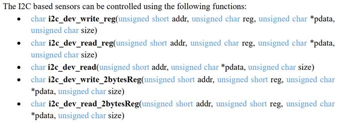
// char i2c_dev_read_reg(unsigned short addr, unsigned char reg, unsigned char *pdata, unsigned char size)
if (i2c_dev_read_reg(i2c_addr, reg, data, 2)) return I2C_ERROR;
*value = ((data[1] << 6) + (data[0] >> 2)); // 8-bit READ_VIN mantissa [9:2]
return 0x00; //return non-zero value in case of reading error (sensor not updated)
}
Then the C file, there is a part, not specific for my sensor,
/* ------------------------------------------------------------------ */
/* This section contains Template sensor methods. */
/* ------------------------------------------------------------------ */
/* Fill the Get Sensor Reading reply */
static char sensor_dcdc_fill_rd(sensor_t *sensor, unsigned char *msg){
/* Get instance index using the pointer address */
unsigned char i, sval, error;
i = ((sensor_dcdc_t *) sensor) - sensor_dcdc;
if (sensor_dcdc_initialized[i]) {
sensor_dcdc_initialized[i] = initialize_sensor_dcdc(sensor_dcdc_ro[i].i2c_addr, sensor_dcdc_ro[i].reg);
}
error = read_sensor_dcdc(&sval, sensor_dcdc_ro[i].i2c_addr, sensor_dcdc_ro[i].reg);
/* Update sensor value */
if (error == 0){
sensor_threshold_update_s(&sensor_dcdc[i].sensor, sval, 0);
}
return sensor_threshold_fill_reading(sensor, msg);
}
My understanding that part is related to the internal IPMC functionality and I’m not supposed to modify it.
You suggest to look at the example the sensor driver code of the temperature sensor on the IPMC here:
https://gitlab.cern.ch/ep-ese-be-xtca/ipmc-project/-/blob/master/ipmc-sensors/sensor_mcp9801.c#L112
The function here is:
static void sensor_mcp9801_update_reading(unsigned char num, unsigned char flags)
is quite different from my:
static char sensor_dcdc_fill_rd(sensor_t *sensor, unsigned char *msg)
It uses the function
monly_i2c_is_ready(addr)
where
addr = PRG_RD(sensor_mcp9801_ro[num].i2c_addr);
I understand, that I have to use this function - monly_i2c_is_ready(addr) in my code, around
error = read_sensor_dcdc(&sval, sensor_dcdc_ro[i].i2c_addr, sensor_dcdc_ro[i].reg);
But I ‘m not sure how to get the (addr) for the monly_i2c_is_ready(addr) as I don’t have the “num”.
So, will be grateful if you can tell me the implementation.
Please, let me know if my question is not clear.
Thank you,
Yuri